Views: 0 Author: Site Editor Publish Time: 2026-09-30 Origin: Site


Many facilities struggle when replacing legacy transmission parts. They rely on outdated specifications instead of current engineering standards. Selecting the wrong specification leads to premature failure and unexpected downtime. These errors compound maintenance efforts across precision mechanical systems. Standardizing components often seems highly efficient at first glance. However, high-torque applications demand the exact alignment of materials and tooth geometry. Engineers must match load thresholds accurately for optimal performance. Overlooking these details usually results in catastrophic drive failures. We provide a comprehensive technical evaluation framework below. This article explains how to specify components correctly. You will learn to balance tooth profile mechanics against operational demands. We will also cover precise load capacity calculations step by step. Following these guidelines guarantees an extended lifespan for your machinery. You can avoid common pitfalls using this structured approach.
Material constraints: Rubber offers superior flexibility and temperature resistance compared to polyurethane, but requires careful evaluation in oil-heavy environments.
Profile selection: Curvilinear (HTD) profiles handle significantly higher torque and reduce ratcheting compared to classic trapezoidal designs.
Capacity calculation: True load capacity relies on dynamic tensioning, belt width, pitch, and the specific tensile cord material (fiberglass vs. aramid).
Risk mitigation: 80% of synchronous belt failures stem from improper tensioning or pulley misalignment, not inherent material defects.
Engineers constantly evaluate operational limits when designing mechanical drives. They must objectively compare chloroprene rubber against a PU timing belt. Polyurethane offers excellent resistance to specific cutting fluids. It also remains exceptionally clean during continuous operation. However, rubber presents distinct mechanical advantages in highly demanding environments. You must understand these underlying chemical differences.
Rubber provides a much broader operating temperature range. Standard chloroprene compounds withstand continuous ambient heat up to 100°C without degrading. Polyurethane typically begins softening at lower temperature thresholds. Rubber also delivers superior inherent flexibility. This flexibility proves absolutely essential when systems utilize small-diameter pulleys. The material bends easily around tight radii without suffering severe flex fatigue. Furthermore, rubber absorbs mechanical shock loads efficiently. It dampens operational vibrations naturally during sudden torque spikes.
You must acknowledge certain environmental trade-offs. Rubber components generate fine particulate dust over prolonged operation. This characteristic makes them completely unsuitable for strict cleanroom environments. Standard rubber also demonstrates lower chemical resistance to harsh petrochemicals. Prolonged oil exposure causes the rubber matrix to swell significantly. Swelling alters the pitch line and ruins precise gear engagement. You must verify chemical exposures before finalizing material selection.
We reach a clear verdict regarding the material baseline. Rubber shines in heavy-duty power transmission belt applications. Facilities prioritize high rotational speeds and thermal variance in these sectors. Continuous operation takes precedence over strict hygiene protocols. Chemical washdowns rarely occur in these rugged industrial settings. You achieve maximum component durability by matching a rubber timing belt to these specific physical conditions.
Selecting the correct tooth profile prevents destructive ratcheting. A synchronous belt relies entirely on precise geometric engagement. We must analyze the dominant profile designs utilized today. Engineers cannot simply swap profiles without replacing the corresponding drive hardware.
Trapezoidal profiles feature distinct flat-topped teeth. Their internal mechanics rely on a straightforward wedging action. These belts best serve legacy mechanical systems and simple low-torque positioning tasks. They also perform adequately in continuous high-speed applications. However, trapezoidal shapes carry significant structural limitations. They remain highly prone to stress concentration right at the tooth root. This concentrated stress eventually causes microscopic base cracks. They also generate much higher decibel noise levels at elevated speeds.
Curvilinear profiles utilize a specialized rounded tooth design. This geometry allows for deeper physical engagement inside the pulley grooves. We strictly recommend HTD profiles for high-torque, heavy industrial applications. Their primary advantage lies in distributing physical stress evenly across the entire tooth surface. This even distribution effectively prevents "tooth jump" under massive loads. You completely eliminate the dreaded ratcheting effect during aggressive startup torque spikes.
Modified curvilinear profiles optimize the original rounded shape further. Their underlying mechanics aim specifically for zero-backlash precision. These modified belts sit perfectly flush inside the corresponding pulley. They best serve CNC machinery and precise robotic actuation units. Positioning accuracy remains absolutely critical in these advanced systems. Engineers specify them when mechanical tolerances allow zero margin for error.
Tooth Profile Type | Primary Geometry | Best Suited Application | Key Limitation |
|---|---|---|---|
Trapezoidal (T-Series) | Flat-topped, wedged | Legacy systems, high-speed drives | High root stress concentration |
Curvilinear (HTD/STD) | Rounded, deep engagement | Heavy industrial, high-torque | Lower maximum RPM limits |
Modified Curvilinear (GT) | Optimized flush rounded | Robotics, zero-backlash CNC | Requires highly precise alignment |
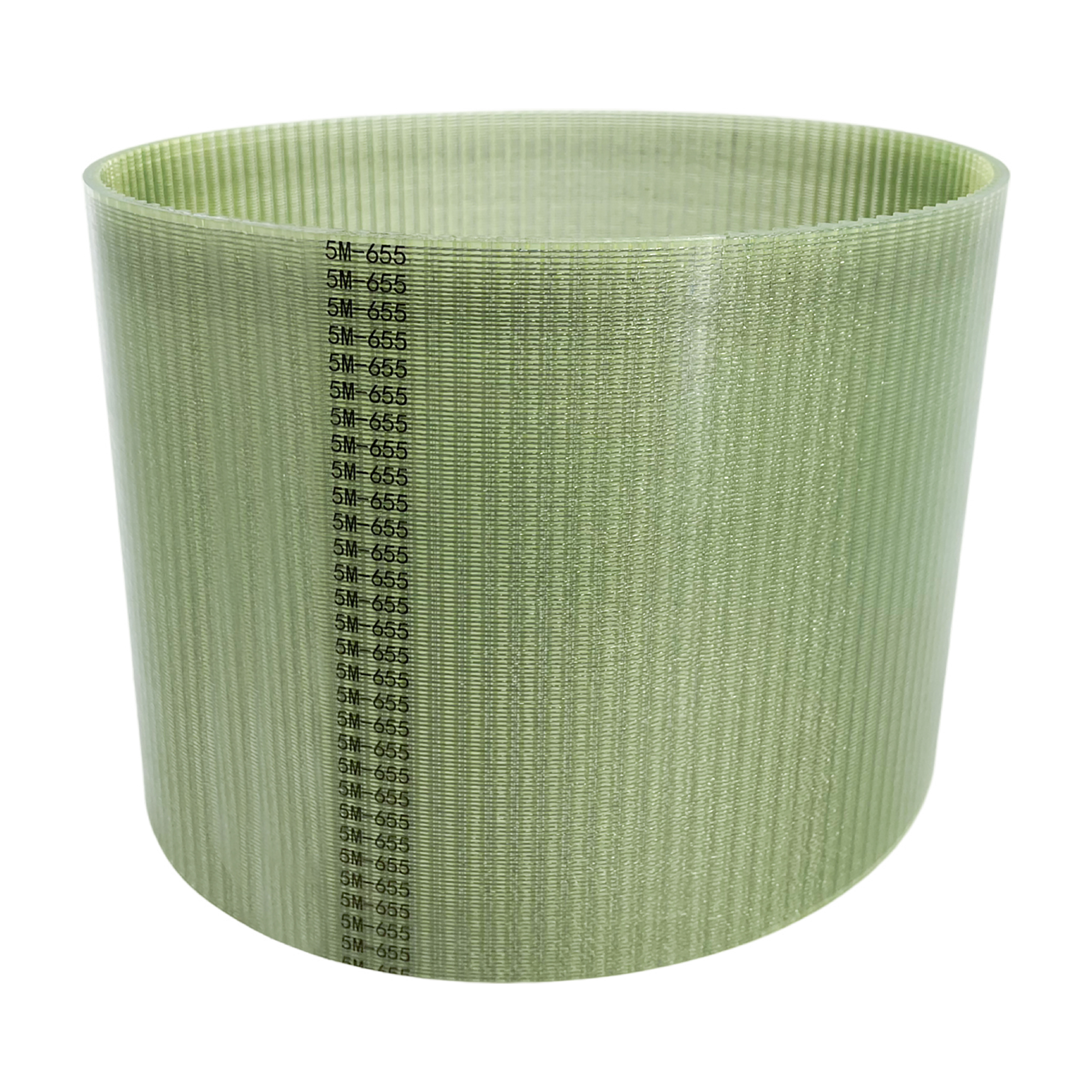
You cannot simply guess the required dimensions for an industrial timing belt. Proper sizing requires rigorous mathematical validation. Engineers follow established formulas to guarantee operational safety.
We always start with the Service Factor Equation. You calculate the true Design Power by multiplying the Nominal Motor Power by a specific Service Factor. This multiplier accounts for unexpected shock loads. It also factors in continuous operation cycles and extreme environmental stress. A smoothly running electric motor might use a 1.2 service factor. Conversely, a heavy industrial rock crusher demands a 2.0 service factor. You must capture these dynamic realities accurately.
Internal tensile cord selection dictates the absolute maximum load limit. The inner reinforcement acts as the true structural backbone. The surrounding rubber merely forms the tooth geometry.
Fiberglass cords: These represent the global industry standard. They offer excellent flex fatigue resistance and extremely low elongation. They handle standard continuous operations perfectly.
Aramid/Kevlar cords: These provide extreme shock-load resistance. They stop catastrophic snapping under sudden jams. However, they remain much less tolerant of small pulley diameters. They require larger bend radii to prevent internal fracturing.
Pitch and width scaling follow strict mechanical rules. Increasing the belt width scales linearly with load capacity. Doubling the physical width essentially doubles the allowable working tension. However, increasing the tooth pitch changes the fundamental torque profile entirely. Larger pitches handle massive torque seamlessly. Unfortunately, they sacrifice maximum rotational speed capabilities. You must balance pitch size against target RPM.
We emphasize total reliance on verified engineering data. You must consult official manufacturer engineering tables. Standard charts from recognized institutions provide essential baseline data. These tables outline precise center distances and strict tensioning tolerances. Never attempt to calculate complex drive geometry without referencing these established standards.
Service Factor Selection Chart | ||
Application Type | Operating Hours/Day | Recommended Service Factor |
|---|---|---|
Uniform Load (Fans, Agitators) | Under 10 Hours | 1.0 - 1.2 |
Moderate Shock (Conveyors, Pumps) | 10 to 16 Hours | 1.3 - 1.5 |
Heavy Shock (Crushers, Mills) | Continuous (24 Hours) | 1.8 - 2.0+ |
Even perfectly specified components fail if installed incorrectly. You must understand how a toothed timing belt degrades over time. Recognizing early diagnostic symptoms prevents catastrophic machinery breakdowns. Maintenance teams must learn these visual clues.
Tooth shear frequently results from severe under-tensioning. The slack belt rides up out of the pulley groove during operation. The tops of the rubber teeth then shear off completely against the metal. This aggressive ratcheting destroys the profile in seconds. Alternatively, you might have selected a specification with inadequate shear strength. The application's sudden torque spikes simply overpower the soft rubber matrix.
Tensile breakage presents very differently. It usually results from extreme over-tensioning by inexperienced technicians. Foreign debris entering the drive enclosure also snaps internal cords instantly. Severe shock loads exceeding the cord's ultimate tensile limits cause sudden breaks. The physical breakage appears jagged, uneven, and highly violent upon inspection.
Edge wear and tracking issues directly indicate severe pulley misalignment. A belt constantly rubbing against the metal flange degrades rapidly. Compromised flange integrity also shreds the exposed rubber edges. You must maintain perfect parallel alignment between the driving and driven shafts. Technicians should use laser alignment tools during initial installation.
We strongly recommend a proactive maintenance mandate. Facilities must establish predictive replacement schedules. Base these critical schedules on actual operating hours. Never wait for obvious visual degradation. Once a rubber component shows obvious surface cracks, failure remains imminent. Replace active components while they still appear physically functional.
Selecting the correct transmission component involves a logical progression. Follow this strict framework to ensure optimal compatibility. Skipping steps inevitably leads to premature mechanical wear.
Define Application Constraints: Document the absolute peak torque and maximum operating RPM. Note the surrounding environmental exposure conditions. Record exact ambient operating temperatures. Identify any chemicals, oils, or harsh abrasives present near the drive system.
Profile & Pitch Matching: Select the specific tooth geometry based strictly on the torque-to-speed ratio. Choose curvilinear profiles for heavy industrial torque. Opt for modified curvilinear profiles if zero-backlash precision matters most.
Sizing the Drive: Calculate the exact required belt width. Determine the actual Design Power using your chosen Service Factor. Refer to standard capacity tables to find the minimum width. This critical step achieves your desired safety margin.
Pulley Compatibility: Ensure the existing pulleys perfectly match your chosen belt profile. Never mix trapezoidal belts with curvilinear pulleys under any circumstances. Incompatible geometries cause immediate rapid wear. They routinely lead to catastrophic system failure upon initial startup.
Your next action should involve specialized technical consultation. Consult with an experienced engineering distributor immediately. Verify all your initial calculations with their technical team. Request detailed technical drawings or prototypes before finalizing your system design.
Specifying a transmission component requires highly technical deliberation. It requires aligning foundational material science, geometric design, and fundamental physics. You must balance rubber characteristics against operational environments. You must also calculate true load capacity accurately using service factors.
We highly recommend prioritizing exact profile matching above all else. Implement rigorous tensioning protocols using proper diagnostic instrumentation. Cheap replacements often destroy expensive custom pulleys. Focus entirely on structural compatibility and alignment precision.
Download a comprehensive sizing chart from a recognized industry manufacturer today. Use proprietary belt-calculation software to verify your specific center distances. Contact a dedicated engineering support team for a custom drive review before finalizing your procurement.
A: Look closely for printed part numbers on the smooth belt back. If faded, measure the exact pitch distance from the center of one tooth to the next. Visually inspect the tooth shape to determine if it is flat-topped or rounded. Compare these physical measurements against standard manufacturer identification charts.
A: Not without completely replacing the corresponding pulleys. The geometric shapes remain entirely incompatible. Mixing different profiles causes immediate rapid wear. It prevents proper tooth engagement and will trigger catastrophic drive failure upon initial startup.
A: Avoid unreliable manual thumb tests. Use a digital sonic tension meter to measure the exact frequency of the free belt span. Cross-reference the resulting Hz reading with the official manufacturer load tables. This guarantees precise dynamic tensioning.