 |


| Quantity: | |
|---|---|
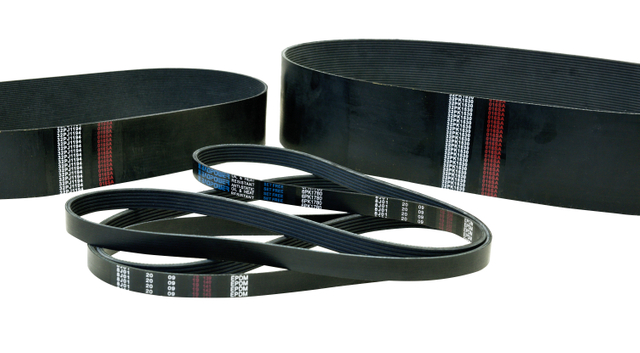
Rubber timing belts utilize a synthetic rubber compound as the base matrix, formulated to maintain dimensional stability under varying load conditions. The compound is blended with specific additives to adjust hardness, friction coefficient, and temperature resistance. The belt body is formed through a vulcanization process that bonds all structural layers into a single integrated unit. Standard formulations operate within temperature ranges of -30°C to 80°C, with specialized compounds available for extended temperature applications.
The tensile member of rubber timing belts consists of high-strength fiber cords embedded longitudinally within the rubber body. These cords carry the primary load during power transmission and determine the belt's tensile strength and elongation characteristics. The cord material and pitch diameter are selected based on the application's power requirements and pulley dimensions. Cord placement is precisely controlled during manufacturing to ensure uniform load distribution across the belt width.
The toothed profile on the inner surface meshes with corresponding grooves on timing pulleys to provide synchronous power transmission. The tooth geometry is engineered to maintain consistent engagement, reducing backlash and ensuring positional accuracy. Standard tooth profiles include trapezoidal and curvilinear forms, each suited to different load and speed conditions. The tooth root radius is optimized to minimize stress concentration during flexing around pulleys.

Parameter | Specification Range |
|---|---|
Model | BP230102 |
Pitch Types | XL, L, H, XH, XXH (trapezoidal); 3M, 5M, 8M, 14M, 20M (curvilinear) |
Tensile Strength | 100 N/mm × 400 N/mm (width-dependent) |
Operating Temperature | -30°C - 80°C (standard compound) |
Max Linear Speed | Up to 50 m/s |
Belt Length Range | 100 mm × 5000 mm |
Rubber timing belts synchronize crankshaft and camshaft rotation in internal combustion engines, ensuring precise valve timing for efficient combustion. They are used in passenger vehicles, commercial trucks, and industrial engine applications. The toothed design eliminates slip, maintaining accurate timing throughout the service interval.
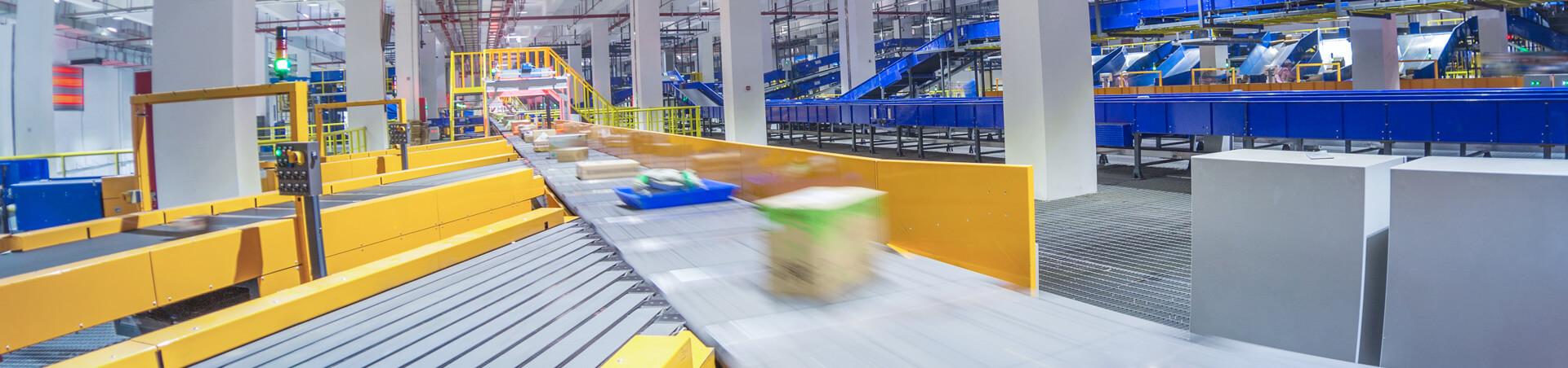
In automated production systems, timing belts drive conveyor indexing, pick-and-place mechanisms, and packaging equipment. Their synchronous operation ensures consistent positioning accuracy, which supports production line throughput and product consistency. Multiple belts can be configured on a single driveshaft for synchronized multi-axis motion.
Textile looms, knitting machines, and printing presses rely on timing belts for precise motion control. The low-noise operation and minimal vibration characteristics contribute to improved product quality in applications where positional accuracy directly affects output.
Selecting the correct tooth pitch is the first step in timing belt specification. The pitch must match the corresponding pulley groove profile to ensure proper meshing. Trapezoidal profiles (XL, L, H) are commonly used for general industrial drives, while curvilinear profiles (3M, 5M, 8M, 14M) offer higher load capacity and smoother engagement for heavier applications.
Belt width selection depends on the transmitted power, drive speed ratio, and pulley diameters. Calculations consider both the static tensile load and dynamic fatigue conditions. Service factors are applied based on load characteristics (uniform, moderate shock, heavy shock) and operating hours per day.
Operating environment influences compound selection. Oil exposure, ozone concentration, humidity levels, and temperature extremes all affect belt material performance. For applications with significant oil contact or extreme temperatures, specialized compound formulations should be specified during the procurement process.
Correct belt tension is critical for service life and transmission accuracy. Insufficient tension can cause tooth jump under load, while excessive tension accelerates bearing wear and reduces belt life. Tension should be measured using a tension gauge and adjusted according to manufacturer specifications for the specific belt width and span length.
Parallel misalignment between driving and driven pulleys causes uneven tooth wear, increased noise, and premature belt failure. Pulley shafts must be aligned within tolerance limits specified for the belt width. Alignment should be verified using straightedge or laser alignment tools during installation.
Timing belts require periodic replacement based on operating hours or visual inspection criteria. Signs indicating replacement need include visible tooth wear, cracking on the belt backside, cord exposure, or significant elongation beyond tension adjustment range. Replacement schedules should be documented as part of preventive maintenance programs.
Standard profiles include trapezoidal (XL, L, H, XH, XXH) and curvilinear HTD (3M, 5M, 8M, 14M, 20M) tooth forms. Custom profiles can be developed for specific application requirements.
Belt size is determined by pitch type, pitch length (number of teeth × pitch), and width. These parameters are calculated based on the transmitted power, speed ratio, pulley diameters, and center distance.
Custom-sized timing belts have a minimum order value of USD 1000. Standard catalog sizes may be available in smaller quantities depending on current inventory levels.
Standard rubber timing belts operate up to 80°C continuously. High-temperature compounds are available for applications up to 120°C. For temperatures beyond this range, alternative belt materials should be considered.
Production lead time for bulk timing belt orders ranges from 25 to 35 days, depending on order volume and specification complexity. Expedited production may be available for urgent commercial procurement requirements.